What kVA, kW, kVAR and power factor mean, how they relate, and how to use them to size cables, breakers, generators and APFC capacitor banks — with worked examples for a 415 V three-phase supply.
Three kinds of power
Alternating-current loads draw three kinds of power. Real power, in kilowatts (kW), does the useful work — turning a shaft, producing light or heat — and is what your energy meter bills in kWh. Reactive power, in kilovolt-amperes reactive (kVAR), is the power that motors, transformers and fluorescent ballasts exchange with the supply to set up their magnetic fields; it does no work, but it still loads the cables and transformers. Apparent power, in kilovolt-amperes (kVA), is the total the supply has to deliver. The three form a right-angled triangle: kVA² = kW² + kVAR².
What power factor tells you
Power factor (PF) is the ratio of real to apparent power: PF = kW ÷ kVA, which is also the cosine of the angle φ between voltage and current. A PF of 1.0 means all the current does useful work. Motor-heavy sites often run at 0.7–0.85, which means that a large share of the current does no useful work but still heats the cables and uses up capacity. Many utility tariffs and consultant specifications therefore ask for a power factor of around 0.9 or better; check the requirement for your project and tariff.
Worked example 1: current from kW
Take a three-phase load of 75 kW on a 415 V supply. At a power factor of 0.80 the apparent power is 75 ÷ 0.80 = 93.75 kVA, and the line current is I = kVA × 1000 ÷ (√3 × 415) = 93,750 ÷ 718.8 ≈ 130 A. If the power factor is improved to 0.95, the apparent power is 75 ÷ 0.95 ≈ 78.9 kVA and the current falls to about 110 A — roughly 16% less current for exactly the same useful power. That freed capacity is why power-factor correction can delay the need to upgrade cables, breakers and transformers.
Worked example 2: capacitor kVAR to correct the power factor
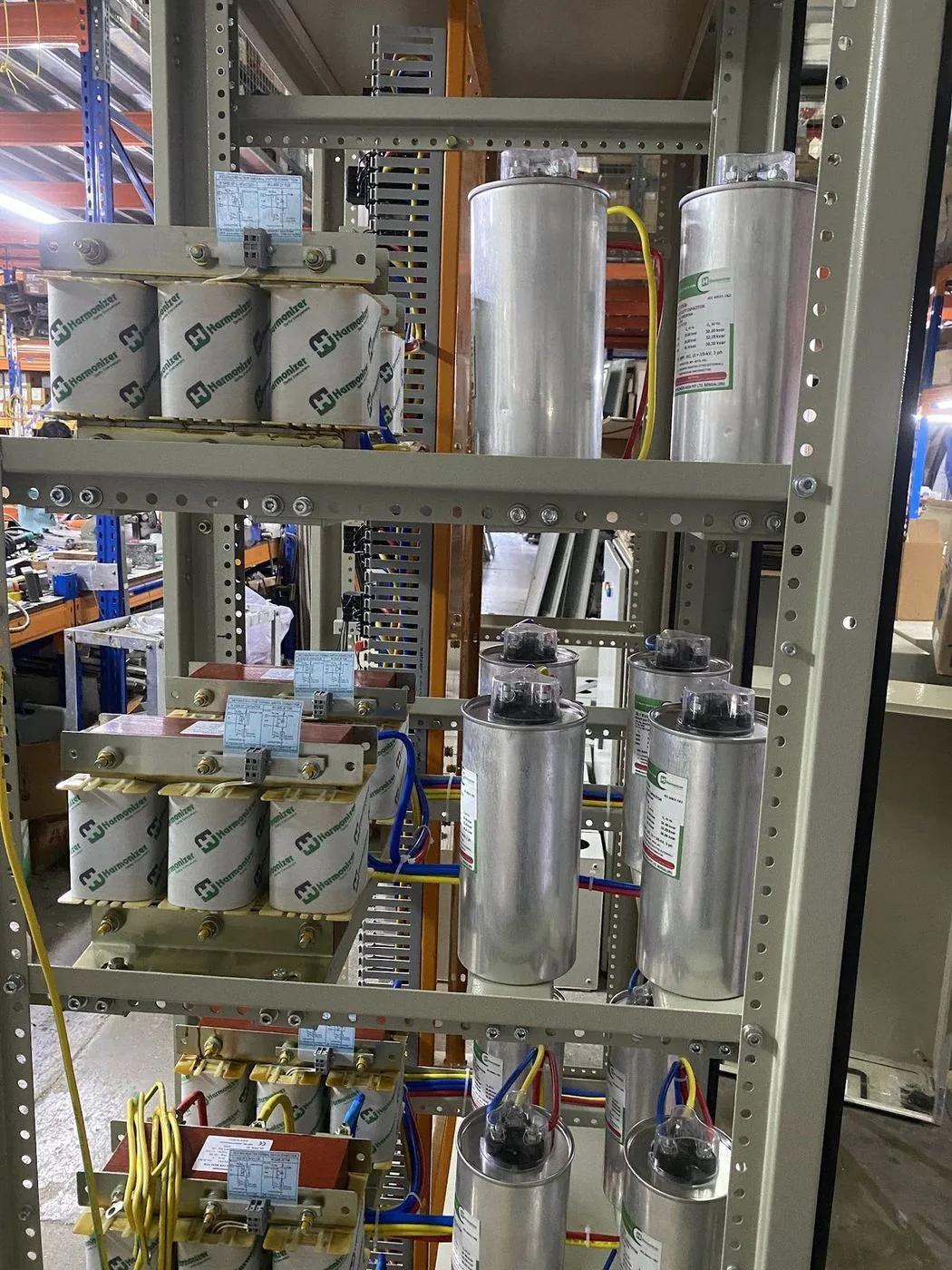
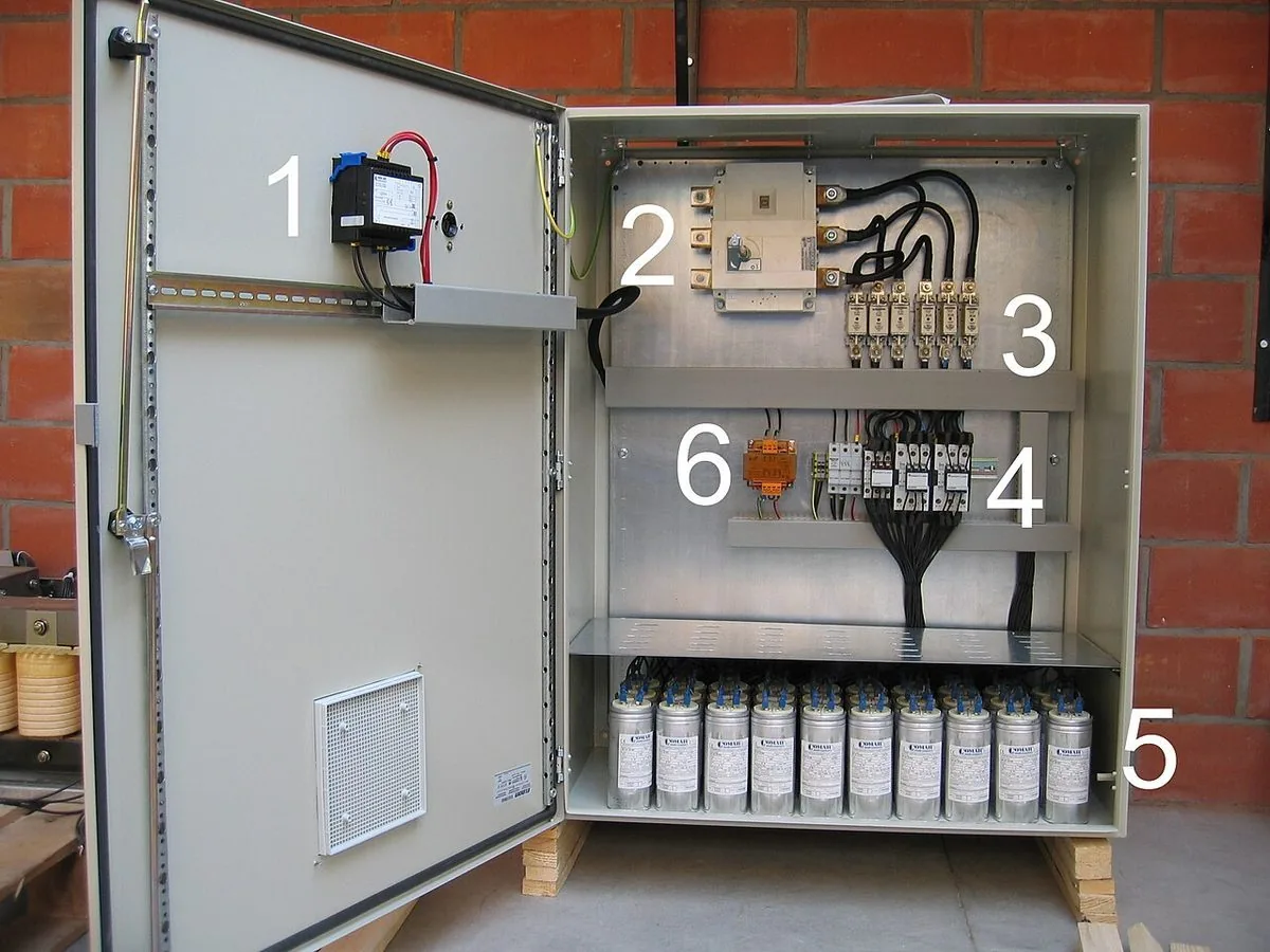
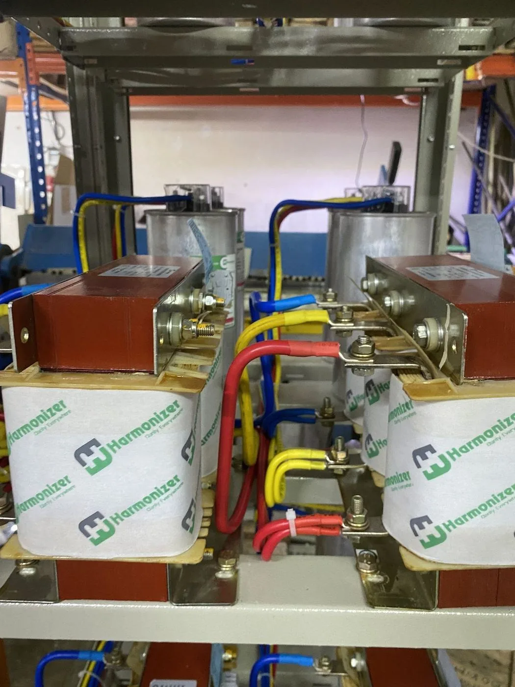
To raise 75 kW from PF 0.80 to 0.95, use kVAR = kW × (tan φ₁ − tan φ₂). At PF 0.80, tan φ₁ = 0.75; at PF 0.95, tan φ₂ = 0.329. The difference is 0.421, so the capacitor bank needs about 75 × 0.421 ≈ 31.6 kVAR. In practice you add a margin and round up to the nearest standard step — for example a 35 kVAR bank built from several switched steps controlled by a power-factor regulator. If the site has harmonic-producing loads such as drives or LED lighting, fit detuned reactors in series with the capacitors. Our guides on capacitor bank sizing and power-factor correction cover the full procedure.
Sizing generators and transformers in kVA
Generators, UPS units and transformers are rated in kVA because their limit is current, and current depends on kVA, not kW. A generator labelled 500 kVA at 0.8 power factor can deliver 400 kW of real power. To size one, add up the real power of the loads, divide by the load power factor to get kVA, add an allowance for the starting current of the largest motor (which depresses the voltage on a weak source), and add some margin for future load. A soft starter or a VFD needs a smaller generator than a DOL motor of the same size, because the starting current is lower.
Sizing panels, breakers and cables
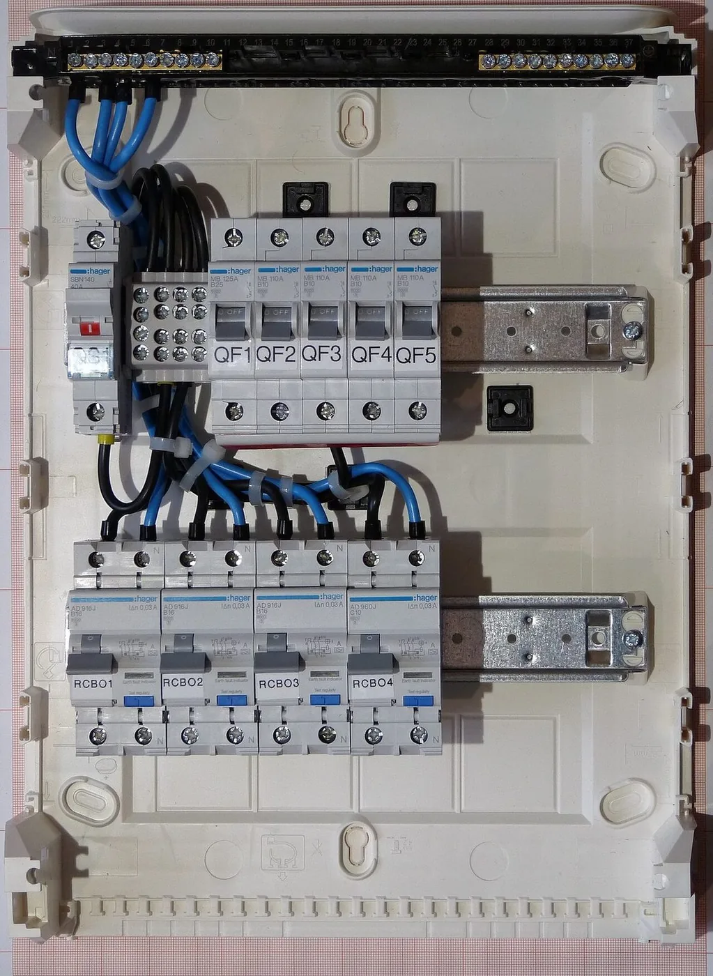
Busbars, incomer breakers and cables are chosen from current. For a 400 kVA load on a 415 V three-phase supply, I = 400,000 ÷ (√3 × 415) ≈ 556 A, so a 630 A incomer would be a natural starting point after applying the diversity of the connected loads and allowing for future growth. Always size on kVA — if you size on kW alone you under-size the equipment for any load with a power factor below 1.0. The maximum-demand and diversity calculator on this site can help you estimate the demand before you choose the incomer.
Measuring the real numbers on your site
The easiest way to know your actual kW, kVA, kVAR and power factor is to measure them. A multifunction meter such as the Multispan MFM series shows voltage, current, power, power factor and energy on one display, and many have RS-485 Modbus output so the values can be logged by a BMS. Take readings at the main incomer over a typical week — including the peak operating periods — before sizing capacitors or ordering a larger incomer. The kVA / kW / Amps calculator and the power-factor (APFC) kVAR calculator on this site do the arithmetic for you.