A practical walkthrough for sizing an APFC capacitor bank on UAE loads — the kVAR formula, step selection, detuned reactors and heat derating — to lift power factor and cut DEWA penalties.
Why correct sizing cuts your DEWA bill
Motors, transformers and lighting ballasts draw reactive power (kVAr) that does no useful work but still loads your cables and transformer. That drags down your power factor — the ratio of real power (kW) to apparent power (kVA). In the UAE, utilities including DEWA expect large consumers to hold power factor near 0.9 lagging or better, and apply a low-power-factor penalty when you fall below it. An APFC (Automatic Power Factor Correction) capacitor bank supplies that reactive power locally. Size it correctly and you clear the penalty, free up transformer and cable capacity, and reduce distribution losses. Size it wrongly and you either under-correct, or overshoot into a leading power factor that causes its own problems.
The core kVAr sizing formula
The reactive power a bank must supply is: Qc = P × (tan φ1 − tan φ2). Here P is the real load in kW, φ1 is the phase angle at your existing power factor, and φ2 is the angle at your target. Because tan φ = tan(arccos PF), you convert each power factor to its tangent and subtract. Most engineers keep a kVAr multiplier table so the tangents are read off directly against the two power factors. The result is the total capacitor kVAr you need at that load point. Always base P on measured demand, not connected load, so the bank is not grossly oversized for the way the site actually runs.
Step 1 — Collect accurate load data
Good sizing starts with real numbers, not nameplate assumptions. Pull the maximum demand in kW and the average power factor from your DEWA bill or, better, from a logging power-quality meter installed for a week or two. Note how the load varies across shifts — a factory with staged motor starts behaves very differently from a steady chiller plant. Record the total harmonic distortion of current (THDi) if the meter reports it, and list the major non-linear loads such as variable-speed drives, UPS systems and rectifiers. This same survey tells you whether one fixed step will do or whether you need automatic switching, and whether harmonics force detuned reactors later on.
Step 2 — Calculate the required kVAr (worked example)
Take a 400 kW load measured at 0.80 power factor, with a target of 0.98. tan(arccos 0.80) = 0.750 and tan(arccos 0.98) = 0.203. So Qc = 400 × (0.750 − 0.203) = 400 × 0.547 ≈ 219 kVAr. You would specify the next standard size up — a 225 kVAr bank. Targeting 0.98 rather than a bare pass at 0.90 gives headroom for load growth and metering tolerance without pushing you into leading territory. If several distinct loads share a board, size against the combined measured demand and power factor, not the sum of individual motor ratings.
Step 3 — Choose the number of steps and resolution
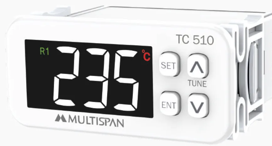
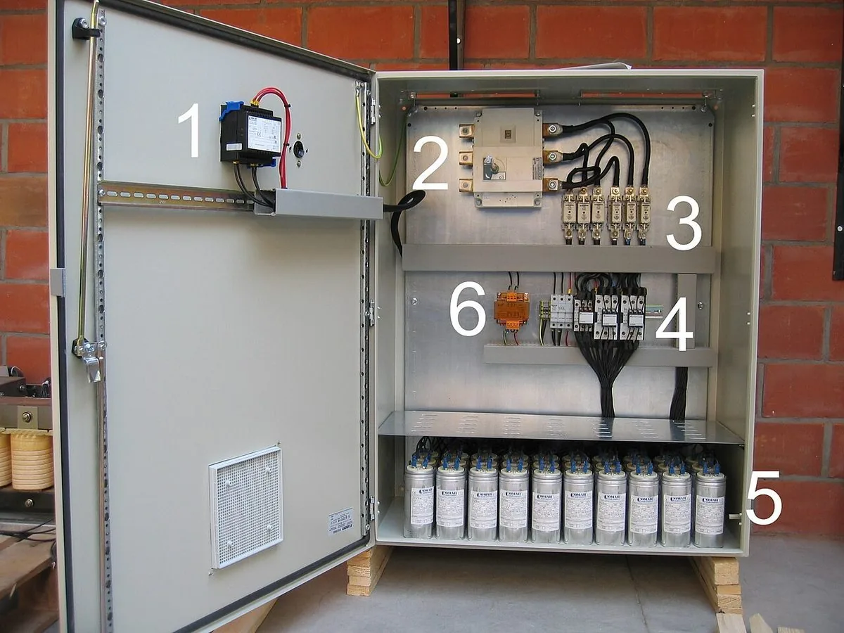
A steady load can use a fixed bank; a varying load needs an APFC panel that switches capacitor stages in and out via a power-factor relay. The number of steps sets the correction resolution — the smallest step is the finest adjustment the panel can make. A 225 kVAr bank might be built as 8 equal steps of about 28 kVAr, or 12 steps for smoother control on a fluctuating load. Smaller first steps help sites that idle at light load, avoiding a jump straight into over-correction. More steps mean more contactors and cost, so match granularity to how much the load actually swings through the day.
Step 4 — Decide if you need detuned reactors
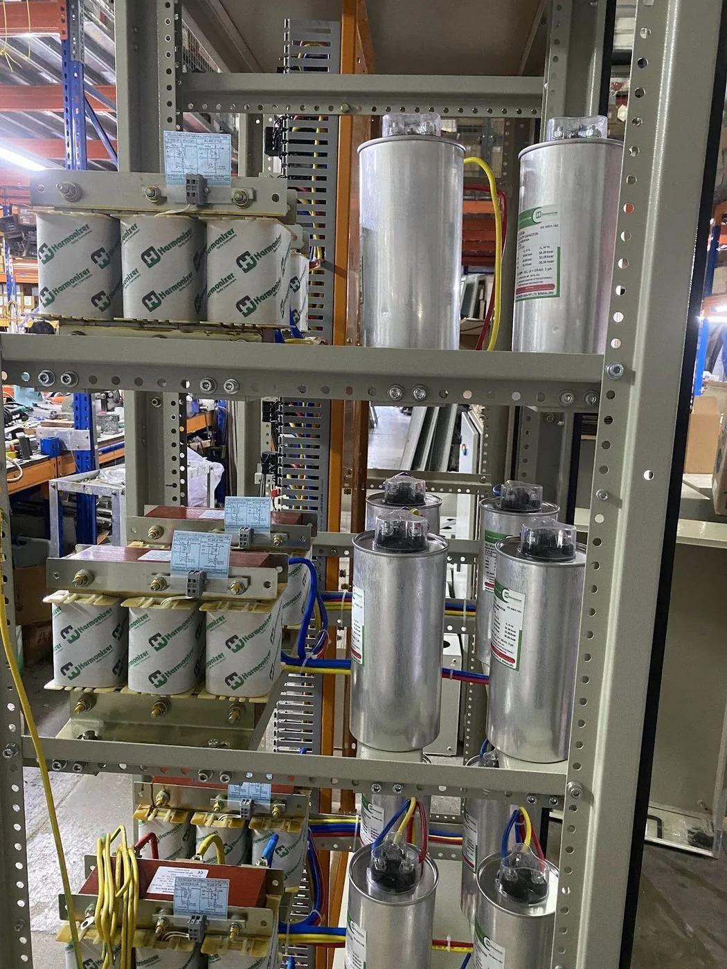
Where non-linear loads are significant — many VFDs, UPS or rectifier loads, or measured THDi above roughly 10–15% — plain capacitors are risky. Capacitor impedance falls with frequency, so they attract harmonic currents and can resonate with the supply transformer, overheating and failing early. A detuned reactor placed in series with each capacitor step shifts the branch resonance below the lowest troublesome harmonic (typically the 5th, at 250 Hz). A common 7% reactor tunes the branch to about 189 Hz, safely below 250 Hz. Detuning raises the voltage across the capacitor, so detuned steps use capacitors rated above the nominal 415 V (commonly 440–480 V) to survive.
Step 5 — Rate for UAE heat, switching and protection
Gulf ambient temperatures routinely exceed the 40–45°C many capacitors are rated for, so choose a suitable temperature category and derate accordingly, with ventilated or force-cooled enclosures. Use capacitor-duty contactors with early-make pre-charging resistor contacts to tame the high inrush when a step energises; ordinary contactors weld shut. Protect each step with HRC fuses and size step cabling generously — IEC 60831 allows continuous current up to around 1.3–1.5 times rated, and harmonics push it higher. These details are where a bank sized correctly on paper either lasts fifteen years or fails in one hot summer, so they belong in the specification from the start.
Common mistakes and payback
The frequent errors are sizing on connected rather than measured load, ignoring harmonics until capacitors fail, and over-correcting into a leading power factor at light load — which can trip protection and disturb voltage. Undersized cables and standard contactors are the next most common. Done properly, power-factor correction usually pays for itself within one to two years through avoided penalties and recovered capacity, before counting reduced losses. If you would rather not run the numbers alone, our team can size and build an APFC bank in Dubai from your load data — with detuned reactors and quality capacitors where the harmonics call for them, custom-built to IEC and DEWA requirements.