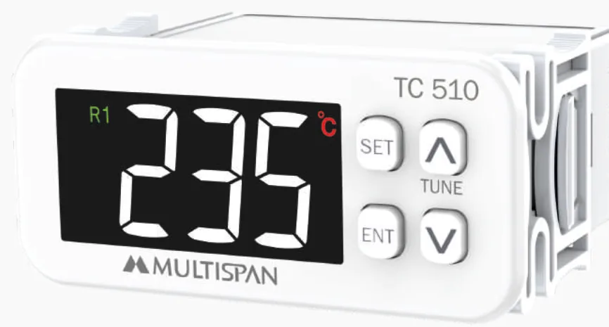
A safe, step-by-step guide to wiring a Multispan panel-mount temperature controller such as the TC 510 — supply, J/K/PT-100 sensor, and relay or SSR output.
Before you start: safety and what you need
Wiring a panel-mount temperature controller is straightforward, but it involves mains voltage — treat it as a job for a competent electrician. Isolate the panel, lock off the supply and verify it is dead with a tester before touching any terminal. Gather the essentials: the controller (we use the Multispan TC 510 as our example, a universal-input model taking J, K and PT-100), the matching sensor and compensating cable, a small flat screwdriver, ferrules, and the wiring label printed on the controller case or in the manual. Always follow the terminal diagram on your specific unit rather than any generic pinout, because layouts differ between models and revisions.
Understand the terminal layout
Every Multispan controller carries a wiring sticker on its housing that groups the terminals into three jobs: auxiliary supply, sensor input, and output. Read this label first and identify each block before stripping a single wire. On a typical TC 510 you will find a two-terminal supply section, a sensor input section (two terminals for a J or K thermocouple, or three for a PT-100 RTD), and one or more output terminals for the relay and, where fitted, the SSR drive. Note polarity markings — thermocouples and PT-100 sensors are polarity- and lead-sensitive. If your unit has extra alarm or communication terminals, leave them until the core connections are proven.
Step 1 — Connect the auxiliary supply
Bring your control supply to the two supply terminals marked on the label. Multispan universal-input controllers commonly accept a wide range around 90–270 V AC, but confirm the voltage band printed on your unit before energising — never assume. Use correctly rated, ferruled conductors and keep the supply pair away from the sensor wiring to limit noise. Do not run the load current through these terminals: they power the controller electronics only, drawing very little current. Protect the supply with a small fuse or MCB, and keep the connections tight — a loose supply terminal is a common cause of intermittent display faults.
Step 2 — Wire the sensor (J/K thermocouple or PT-100)
For a J or K thermocouple, connect the two sensor leads to the thermocouple input terminals, observing polarity — reversed leads make the reading move the wrong way. Use the correct compensating/extension cable for the couple type all the way back to the controller; ordinary copper introduces error. For a PT-100 RTD, use the three-wire connection to the three input terminals so lead resistance is compensated, keeping the three cores the same length. Then select the matching input type in the controller menu (J, K or PT-100) — on a universal unit this is a software setting, so the wiring and the configured type must agree. Route sensor cable away from power and contactor wiring.
Step 3 — Wire the output to your load
Match the output stage to what you are switching. The relay output suits contactors, solenoid valves and resistive heaters at moderate switching rates; wire the load through the relay contact terminals and confirm the contact current rating covers your load, adding a contactor if it does not. The SSR output does not switch power directly — it provides a low-voltage DC drive signal to an external solid-state relay, which then switches the heater. This pairing is the right choice for fast, high-cycle heating where PID modulation demands frequent switching. Never connect mains load directly to the SSR-drive terminals, and fit suppression across inductive loads.
Step 4 — Power up, configure and test
With every terminal double-checked and the panel closed, restore the supply. The controller should light up and show the process value. Enter the setup menu to confirm the input type matches your sensor, choose your control action (on/off for simple duties, PID for tight control), set the setpoint, and pick relay or SSR as the active output. Run Auto-Tune if you are using PID so the controller learns your process. Test at low risk first: watch the reading track a known temperature, confirm the output energises below setpoint for heating and de-energises above it, and check the output LED follows the logic before committing the plant to automatic running.
Safe practices and common wiring mistakes
A few habits prevent most call-backs. Keep sensor cables physically separated from power and contactor wiring, and earth the panel and any cable screens properly to keep readings stable. Do not reverse thermocouple polarity or mix couple types with the wrong compensating cable. Do not drive a contactor coil or heater straight from the SSR-drive terminals — that output is a signal, not a power contact. Always set the menu input type to match the sensor you physically wired. Torque terminals to the label figure — over- or under-tightening both cause trouble — and re-check them after the first heat cycle, when connections can settle.
Need help or a genuine replacement?
As the authorized Multispan distributor for the UAE and GCC, we can confirm the correct model for your sensor, control action and load, supply the matching datasheet and wiring diagram, and recommend a drop-in replacement if you are upgrading an older controller. If you are unsure which input or output stage your panel needs, send us your process details and the model number of any unit you are replacing, and our team will guide the wiring and specification. We deliver genuine Multispan instruments across all seven emirates and the wider GCC.